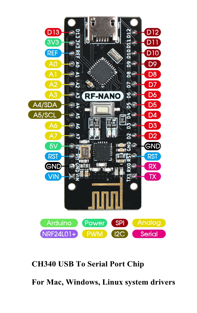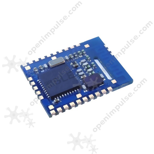
Here comes the second member in the DFRobot Bluno family, the Bluno Nano. Came in the size of a gum, the Bluno Nano is perfect for BLE projects with limited space or weight. You may also check the Bluetooth microcontroller selection guide to get more information.
Everything is getting smart now: wristbands and watches monitor your daily behaviors and become social; phone-controlled camera add-ons move and take shots as you like; smart gardens grow virtually in your iPad and sharing is made easy... The Bluetooth Low Energy technology has made it easy and achievable. It is exciting to see more and more smart gadgets poping out, but, isn't building own smart device and solving your own problems even cooler?
To find the latest driver for your computer we recommend running our Free Driver Scan. TI CC2540 USB CDC Serial Port (COM3) - Driver Download. Vendor: Texas Instruments. The package provides the installation files for Arduino Mega 2560 Board USB Driver version 1.1.1.0 If the driver is already installed on your system, updating (overwrite-installing) may fix various issues, add new functions, or just upgrade to the available version. An TI CC2540 chip on the board channels this serial communication over USB and the TI CC2540 chip drivers (included with the Arduino software) provide a virtual com port to software on the computer. The Arduino software includes a serial monitor which allows simple textual data to be sent to and from the Arduino.
DFRobot's Bluno family is the first of its kind in integrating BT 4.0(BLE) module into 'Arduino Uno', making it an ideal prototyping platform for developers to go wireless. You will be able to develop your own smart bracelet, smart pedometer, and more. Through the low-power Bluetooth 4.0 technology, real-time low energy communication can be made really easy.
Bluno Nano also integrates a TI CC2540 BT 4.0 chip with the 'Arduino UNO' development board. It allows wireless programming via BLE, supports Bluetooth HID, supports AT command to config the BLE, and you can upgrade BLE firmware easily. Bluno is also compatible with all Arduino Uno pins which means any project made with Uno can directly go wireless! Whatsmore, we also developed the App for the Bluno (both Android and IOS), and they are completely open-source so that you can modify and develop your own hardware-software platform.
Note: For expanding I/O ports, the Bluno Nano is compatible with all Arduino-Nano-compatible expansion shields. If you want to use Bluno Nano via other expansion shields, some extra wirings will be needed.

Version patch
- v1.3 - Improve the design of antenna to support up to 50m BLE communication by two Bluno nano
Ti Cc2540
As part of my University Final Year Project (FYP), I needed to interface a digital weighing scale. This is something that has definitely been done before but there’s not too much documentation available on it. Therefore, I humbly present my guide to interfacing a digital weighing scale with a microcontroller.

Firstly, an overview of the main component (or components, in some scales) of any digital weighing scale – the load cell. Wikipedia has a pretty good article on load cells, but essentially these are transducers that convert force into an electrical signal. The load cell in a a typical digital scale typically takes the form of either an aluminium bar with a white epoxy blob with four wires coming out of it, or an aluminium fitting with the same epoxy blob but only three wires (there are other types, including a flat piece of metal with a U shape cutout. These are usually found in scales with more than one load cell, making them far more complicated to interface). These different types correspond to full- and half- Wheatstone Bridges respectively. I’ll focus on the former as this is what I worked with.
The device I have was taken from an Argos Value Range weighing scale I bought for around five euro. It’s a basic scale with a range of 0-5 KG in 1 gram increments, that I chose due to the type of load cell it contained. This device was chosen as (a) it was cheap and (b) it used a single, four-wire cantilever-style load cell rather than four three-wire load cells with one on each foot of the device (more on this later). An image of the device with the load cell fitted is given below, but load cell aside, this scale is probably no different to any other digital scales on the market and any scale with a similar type of load-cell will do.
The Argos Value weighing scales with the load cell visible
Upon cracking it open, it is possible to four-wire load cell. This is the aluminium bar with the white blob of epoxy that protects the strain gauges that the system relies on from the elements.
Proceed to open it up even more until the PCB (circuit board) is accessible.
The PCB in closer detail
Once you can get to the PCB, unsolder all the wires from the PCB and leave it to one side – it isn’t needed anymore. While doing so pay attention to the names of each solder point. In the case of this scale, the wires of particular import are those on the top right corner: E+ (red), E- (black), S+ (green) and S- (white); or excite+,excite-,sense+andsense-“. These should be the four wires coming from the load cell and the names tell you the function of each wire (needed later).
At this point, I’d advise soldering solid-core wire or jumper cables to the load cell wires. This will make it easier to work with on a breadboard.
Cc2540 Driver Arduino Programming
There are four wires coming from the cell – red, black, green and white – that correspond to the excite positive and excite negative (power), and sense positive and sense negative (sensor) wires respectively. These wires correspond to the varying points in a Wheatstone bridge and this is illustrated below.
Before beginning any real circuit work, you must first find out what you’re working with. In my case, I connected the device in the manner seen below – connecting a 5v supply to excite+ (red), 0v/ground to excite- and a multimeter to sense+ (green) and sense- (white) at different intervals. By doing this, it became evident that, while the scale was at rest, the voltages from both outputs were almost identical at half the input voltage (2.5v). As explained above, and hence as expected, the voltage level on the green sense+ wire increased with pressure while the voltage level decreased on the other white sense-. However, what was worth noting was the level of voltage change. Despite apply as much pressure as possible with my thumb I could only get each wire to register a voltage change of roughly +/-6mV. This is a trait of load cells and, more specifically, strain gauges – their resistance changes with stress and strain, but only slightly.

The voltage differences seen across the sense wires are obviously too minimal to be recorded by a typical ADC. A 12 bit ADC has 2^12 possible levels, meaning each level corresponds to a 5v/(2^12) increase/decrease in voltage, or ~1.22mV. Any change in voltage across the sense wires is more likely to be measured in a fraction of millivolt (the precise change in voltage is usually given in the datasheet when you buy a load cell by itself but it is quite easy to calculate through some experimentation, if you so wish). However, in any case your typical ADC is not going to have any accuracy when reading values that change as little as these do – they’re just too small. What we need to do is amplify (a.k.a. increase the voltage level of) the signals or, more precisely, the difference between the two.
This can be done a number of ways but the two that spring to mind are the differential op-amp (a.k.a. subtracting op-amp) or an instrumentation amplifier. There are plenty of guides available on the internet for how to build a differential op-amp circuit using chips like the LM358, and this will allow you to multiply the difference in two voltage levels by a set amount (the gain). However, while they will work for larger signals, they typically won’t be all that precise for signals this small. A much better option is to purchase an instrumentation amplifier IC (chip), as these offer high precision, high input impedance and a simple method for changing gain.
The Analog Devices AMP04 is one such example. (Note: Do NOT try this with the AMP02. This is a dual supply op-amp meaning it expects a voltage on the V+ pin and the negative of that voltage on the V- pin (i.e. +15v and -15v). This probably isn’t what you want here. The AMP04 is a single-supply/single-rail op-amp and is suitable for a 5v – ground setup)
Ti Cc2540 Dongle Driver
AMP04 Pinout, taken from the Analog Devices datasheet
You’ll want to wire this as follows:
Arduino Cc2530
- Connect ground to the
v-pin - Connect the 5v supply to the
v+pin - Connect a suitable resistor between the two
Rgaininputs hence controlling the gain. The formula to calculate the value of this resistor can be found in AMP04 datasheet - Connect the green wire of the load cell to the
+Ininput - Connect the white wire of the load cell to the
–Ininput - Connect the
Voutpin to the ADC input of your ADC port microcontroller (i.e. Arduino)
Cc2540 Driver Arduino
Following this, you should be able to interface the load cell using your microcontrollers ADC, like any other analog sensor. In the case of the Arduino – by using the analogRead() function. I’ll leave this as an exercise for the reader!